Chapters:
Back to family picture index
June 2007
July-August 2007
Sept 2007 plus most of October
Oct-Nov 2007 including Hawaii trip
Dec 2007 and January 2008
February / March 2008
May 2008
June 08
July 08
August 08
September 2008
Remodel pictures
October 2008
November & December 2008
Remodel--footings positions
More remodel pictures
Remodel--Latest plan drawings
January thru March 2009
April & May
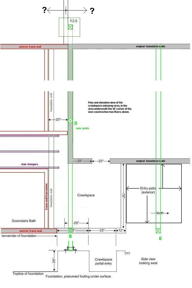
Plan and elevation view of the crawlspace entryway area, in the area underneath the SE corner of the new construction two floors above.
This shows the southern beamline running E-W, taken with the camera pointing east. There are possibly three existing weight bearing columns, one in the white column having the lightswitch and thermostat, and then two on either side of the closet towards the background. We suspect the first of these is a 6x6 sitting on the foundation, whereas the 2nd two are probably lightweight 4x4 or doubled 2x4's. The last of these is inside the exterior wall past that far corner beyond the closet door.
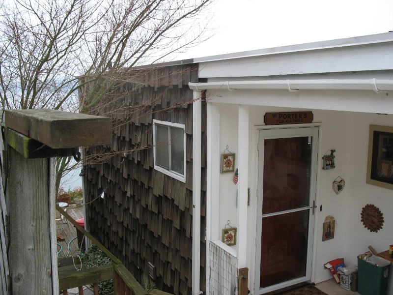
This view is on the exterior. The load-bearing column for the SE corner of new construction is approximately 1 foot leftwards of the small white-trimmed window at the middle of the picture.
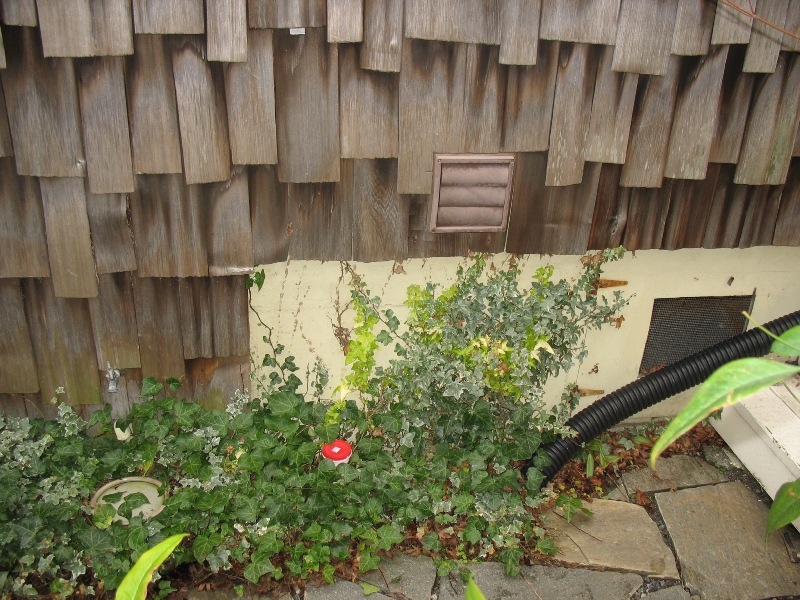
The red plastic container is approximately where the load bearing column would land. It's on the left side (viewed from exterior) of an approximately 38-inch wide section of the 6" perimeter foundation that 25 inches higher than the general top line of the foundation. (See drawing). The landing zone of the column is labelled "B" in the drawing. Note there could be some measurement error because point "A" and "B" are hypothetically lined up. Also in this picture is the crawlspace entry portal (behind black plastic pipe).
Shows the corner of the interior section of the foundation, the vertical left edge corresponds to point "A" on the drawing. You can see the angle of the stair stringer to the left middle. To the left is the rear of the structure enclosing the downstairs bathroom.
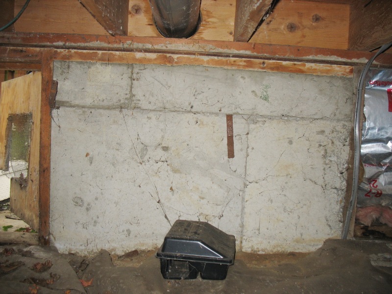
Shows the 38x25-inch vertical extension of the perimeter foundation. The foundation appears to be the 6-inch width seen elsewhere, most likely with the 12-inch footing somewhere under the soil line.
A detail of the right edge of the section in the previous picture. To the lower right, note the retaining wall heading perpendicular from the exterior wall line. Please send an E-mail if you have any comments or corrections, or know something we don't!